Keyence LS-7000 User Manual
Browse online or download User Manual for Sensors Keyence LS-7000. KEYENCE LS-7000 User Manual
- Page / 192
- Table of contents
- TROUBLESHOOTING
- BOOKMARKS
- LS-7000 Series 1
- General precautions 2
- Safety Precautions 3
- ■ Precautions for LED 5
- Ferrite core 6
- OP-31973 6
- About this Manual 7
- Optimum Measurement Methods 8
- Configuration of Manual 9
- LS-7001 Operation Map 10
- Hold function (See page 3-5) 11
- Contents 12
- Chapter 4 Function Settings 13
- Chapter 7 RS-232C 14
- Chapter 8 Specifications 14
- Chapter 9 Troubleshooting 14
- Appendix 14
- Chapter 1 15
- ■ Special Features 16
- ■ Principle of Measurement 16
- System Applications 17
- Package Checks 18
- Chapter 1 Getting Started 19
- Functions and Nomenclature 21
- ■ Control Panel 22
- Mounting and Connection 25
- 2 Mount the measuring head 26
- Mounting the Controller 27
- ■ Mounting to Panel 28
- Connection 31
- ■ Transmitter and Receiver 32
- ■ Power Supply Cable 32
- Supply Stand On and Off 33
- Measurement and 33
- Chapter 2 37
- Set value 38
- Measurement of Pitch 44
- Chapter 3 45
- Chapter 3 Operation Control 46
- Chapter 3 Operation Control 47
- Area Monitor 48
- Hold Function 49
- Automatic Zero Function 50
- Panel Lock Function 51
- Program Changes 52
- Chapter 4 53
- Flow of Program Settings 54
- External I/O 55
- Output Settings 55
- Measuring Mode Settings 55
- Option Settings 55
- ■ Program Initialization 58
- (See page 4-15) 60
- (See page 4-16) 60
- (See page 4-17) 60
- (See page 4-18) 60
- (See page 4-14) 60
- Area Selection 61
- ■ SEG (Segment) 62
- ■ Setting Procedure 64
- DIA (Diameter) 65
- T-EDGE (Top edge) 65
- B-EDGE (Bottom edge) 65
- SEG (Segment) 65
- 6 Press the 69
- Calibration Settings 72
- 5 Press the 77
- Measuring mode 85
- Analog Output Settings 96
- ■ Analog update mode 98
- Comparator Output Setting 99
- (Normally open) 100
- (Normally closed) 100
- 1 Press the 101
- 2 Press the 101
- 4 Press the 101
- Tolerance (LIMIT) Settings 102
- Limit Settings 103
- Hold Value Elimination 104
- 1 Continue pressing the 105
- Chapter 4 Function Settings 107
- 3 Press the 108
- Display Unit 109
- I/O Mode 111
- Chapter 5 115
- Possible Environment Settings 116
- This part changes 118
- ■ Resetting All Programs 120
- ■ RS-232C Settings 121
- ■ Baud Rate 121
- ■ Parity 121
- ■ Stop Bit 122
- ■ Data Length 122
- ■ Data Mode 122
- ■ Data Transmission Mode 123
- The buzzer turns ON 126
- The buzzer turns OFF 126
- Chapter 6 129
- Connector I/O 130
- Terminal block 130
- Chapter 6 I/O Terminals 131
- Chapter 6 I/O Terminals 134
- ZERO Input 6-3, 6-5, 6-6 135
- ■ FUNCTION Output 136
- Electrical Specifications 137
- ■ NPN Open Collector Output 2 138
- ■ Analog Voltage Output 138
- Timing Chart 139
- ■ Sample Hold 2 140
- ■ Self-timing Hold 140
- ■ BCD Output Switching 141
- ■ Minimum Input Period 142
- Chapter 7 143
- Specifications 144
- ■ RS-232C Connection Settings 145
- ■ Environment Settings 146
- Connecting to KV Series 147
- Outline of Command Formats 148
- Measurement Serial Commands 149
- Commands in Detail 150
- ■ Measured Value Output 150
- Chapter 7 RS-232C 151
- Response 153
- Setup Serial Commands 154
- ■ Area Check 156
- ■ Calculation 156
- ■ Average 156
- (Page 7-15) 161
- Batch Commands 162
- ASCII Table 164
- ■ Output 165
- TIMING input 166
- Sampling period + 3.5 ms 166
- RS-232C data output 166
- Chapter 8 167
- Measuring Head 169
- Optional Accessories 169
- Characteristics 170
- Temperature Characteristics 171
- ■ Measurement Response Time 172
- Mode Specifications 173
- External Dimensions 174
- ■ LS-7030 Measuring Head 175
- ■ LS-7070 Measuring Head 175
- ■ Extension Cable 176
- Chapter 9 177
- Troubleshooting Guide 178
- Chapter 9 Troubleshooting 179
- 2 Continue pressing the 182
- Appendix-2 183
- Appendix-3 183
- Appendix-5 183
- Setting Record Sheet 185
- Threshold 186
- WARRANTIES AND DISCLAIMERS 191
Summary of Contents
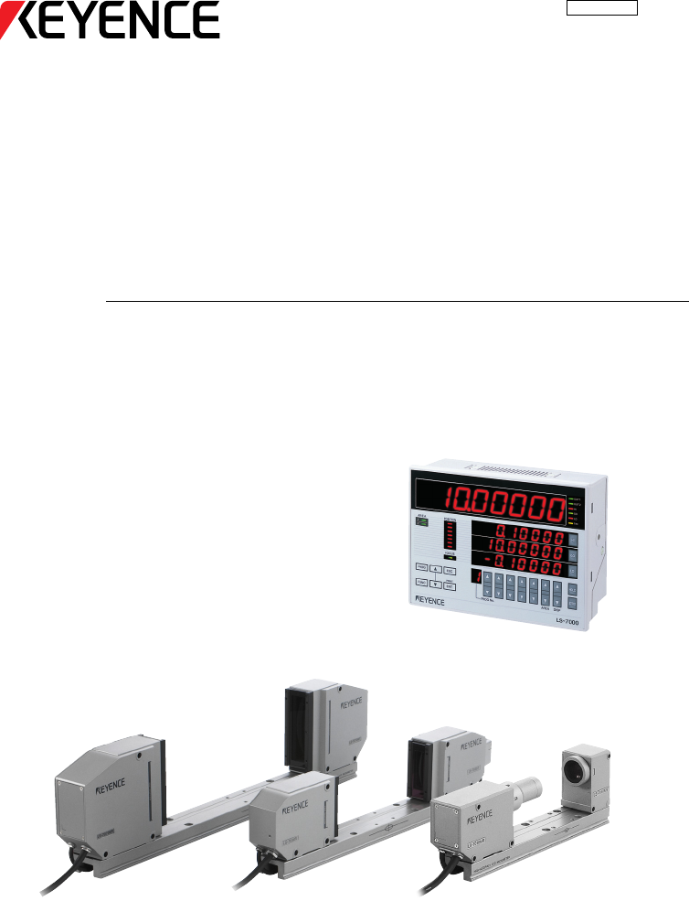
User’s ManualHigh-speed, High-precision Digital MicrometerLS-7000 Series96M12219
viiiNo.Measured vaMeasured vabetween the rand thresholdsetting. (See paPress the DISPLS-7001 Operation MapPROG No.PRINTESCPROGFUNCENTFOCUS21AREAPOSITI
4-48Chapter 4 Function Settings4 Strobe Output TimeTake the following steps to set the ON-time of strobe output.1 Press the ENT key when the outputs
4-49Chapter 4 Function Settings4 OFF-delay TimeTake the following steps to set the OFF-delay time for comparator output.1 Press the ENT key when the
4-50Chapter 4 Function Settings4Tolerance (LIMIT) SettingsThe LS-7000 Series judges whether or not the measured values pass the criteria. Therange of
4-51Chapter 4 Function Settings4Limit SettingsTake the following steps to make tolerance settings in reference value mode or thresholdmode.Refer to S
4-52Chapter 4 Function Settings41 Press the key corresponding to thetype of tolerance to be set.The corresponding tolerance itemflashes. The followin
4-53Chapter 4 Function Settings4Possible Setting Conditions● Reference Value in Tolerance ModeReference value + Lower limit hold value < Reference
4-54Chapter 4 Function Settings4Option SettingsSettings, such as display unit and I/O terminal mode, are available on the LS-7000 Series.Option Setti
4-55Chapter 4 Function Settings4Flow of Option setting DisplayTIMLOGOHIOUT 2OUT 1PROG No.PRINTAREA DISPLS-7000ESCPROGFUNCENTHOLDZEROFOCUS21AREAPOSITI
4-56Chapter 4 Function Settings4Tolerance Mode (LIMITS)Take the following steps to select the appropriate tolerance mode.Setting RangeThe following m
4-57Chapter 4 Function Settings41 Press the ENT key when the optionsetting is displayed.2 Press the FUNC key.3 Press the or key and set thetiming
ixHINo. AREA DISPLS-7000HOLDZEROHIGOLOTIMLOGOOUT 2OUT 1Measured value display selectionMeasured value display varies between the reference value mode
4-58Chapter 4 Function Settings43 Press the or key and set thedisplay unit.The following displayed items can beselected.mmμmGOGOinchmilGOGOTo cha
4-59Chapter 4 Function Settings41 Press the ENT key when the optionsetting is displayed.2 Press the FUNC key three times.HIGOLO3 Press the or key
4-60Chapter 4 Function Settings4Units, Default Minimum Values, and Setting Ranges0.00001mm0.01μm0.00000mm0.00μm+30.00000mm+30000.00μm0.00000mm0.00μm+
4-61Chapter 4 Function Settings40.0000005inch0.01mil0.000000inch0.000mil+3.000000inch+3000.000mil0.000000inch0.000mil+4.000000inch+4000.000mil–0.9999
4-62Chapter 4 Function Settings4MEMO
5-1Chapter 5Environment SettingsThis section provides information on environment settings thatinclude RS-232C interface settings along with basic oper
5-2Chapter 5 Environment Settings5Possible Environment SettingsThe following environment settings are possible.• Program: Program setting changes, pr
5-3Chapter 5 Environment Settings5 Head (See page 5-10)Item Setting rangeLED inspection function (L-INSPCT)(–) HEAD1, HEAD2 (Connected head number)M
5-4Chapter 5 Environment Settings5Flow of Environment Setting DisplayTIMLOGOHIOUT 2OUT 1PROG No.PRINTAREA DISPLS-7000ESCPROGFUNCENTHOLDZEROFOCUS21ARE
5-5Chapter 5 Environment Settings5Details of Environment SettingsThis section provides information on environment setting items and setting methods.P
xContentsSafety Precautions ...iPrecautions
5-6Chapter 5 Environment Settings51 Press the ENT key when the program display is on the screen.2 Press the FUNC key.3 Press the or key to select
5-7Chapter 5 Environment Settings5RS-232CTake the following steps to make the communication settings for the RS-232C interface andrelative settings f
5-8Chapter 5 Environment Settings53 Press the or key and select the parity.The following displayed items can be selected.NoneEvenOddGOGOGO4 Press
5-9Chapter 5 Environment Settings53 Press the or key and select the data mode.The following displayed items can be selected.NonePLCPrinter 1Print
5-10Chapter 5 Environment Settings5HeadTa ke the following steps to set the LED inspection function and mutual interference preven-tion function.Sett
5-11Chapter 5 Environment Settings5Check on Fluctuation of Light Intensity Due to Dirt or DustTo check the dispersion of the amount of light, record
5-12Chapter 5 Environment Settings5 Mutual Interference Prevention FunctionThis function prevents mutual interference that may result when two measu
5-13Chapter 5 Environment Settings5Panel LockTake the following steps to specify the panel lock range when the panel lock function is set.Setting Ran
5-14Chapter 5 Environment Settings5MEMO
6-1Chapter 6I/O TerminalsThis section provides information on I/O terminal specificationsand timing charts.Nomenclature and Functions of I/O Terminals
xiChapter 4 Function SettingsFlow of Program Settings ...
6-2Chapter 6 I/O Terminals6Nomenclature and Functions of I/O TerminalsThis section provides nomenclature and functions of the I/O terminals of the LS
6-3Chapter 6 I/O Terminals6I/O Signal Names and DescriptionsThe I/O terminals handle the following signals. Refer to Function on page 6-7 for thefunct
6-4Chapter 6 I/O Terminals6Connector I/OConnector I/O signals operate in either SUB mode or BCD. Refer to I/O Mode on page 4-59 for details.Applicabl
6-5Chapter 6 I/O Terminals6SUB ModeTerminal numberCable colorSignal name Description123456789101112131415161718192021222324252627282930313233343536373
6-6Chapter 6 I/O Terminals6BCD ModeTerminal numberCable colorSignal name Description12345678910111213141516171819202122232425262728293031323334353637
6-7Chapter 6 I/O Terminals6FunctionsThe following section provides information on I/O signal functions. For the arrangement ofeach terminal, refer to
6-8Chapter 6 I/O Terminals6The following table shows a list of program numbers and the status of the P1 terminalthrough the P4 terminal.Program numbe
6-9Chapter 6 I/O Terminals6 BCD OutputName Description Reference page6-66-66-66-66-6BCD POLE output BCD polarity output.OFF: PositiveON: NegativeBCD
6-10Chapter 6 I/O Terminals6 NPN Open Collector Output 2Output+5V+5V470Ω10kΩ10nF10kΩCOM2Internal circuitMax. applied voltageMax. sink currentResidua
6-11Chapter 6 I/O Terminals6Timing ChartThis section provides information on the timing charts of BCD output in a variety of meas-uring modes. Normal
xiiChapter 6 I/O TerminalsNomenclature and Functions of I/O Terminals ... 6-2Ter minal Block
6-12Chapter 6 I/O Terminals6 Sample Hold 2ONOFFTIMING inputONOFFRESET/ZERO inputONOFFP1 input to P4 inputONOFFComparator outputONOFFWAITING outputON
6-13Chapter 6 I/O Terminals6 BCD Output Switching0±0.1msONOFFBCD SELECT inputONOFFBCD DATA outputONOFFBCD INDICATE outputOUT1 Measured valueON
6-14Chapter 6 I/O Terminals6 Minimum Input PeriodRefer to the relevant timing charts for the delay time (response delay time) in responseto input.N
7-1Chapter 7RS-232CThis section provides information on how to connect the LS-7000 Series to external devices along with RS-232Ccommunications functio
7-2Chapter 7 RS-232C7SpecificationsThe LS-7000 Series has RS-232C communications functions. The following section pro-vides information on the RS-232
7-3Chapter 7 RS-232C7 RS-232C Connection SettingsMake the following environment settings according to the connecting device. For details,go to the r
7-4Chapter 7 RS-232C7Communication using Serial CommandsTo enable the LS-7000 Series to transmit measured values or allow setting changes,connect a p
7-5Chapter 7 RS-232C7Connecting to KV SeriesThe following information provides information on how to connect Keyence’s KV-seriesProgrammable Logic Co
7-6Chapter 7 RS-232C7Outline of Command FormatsWhen LS-7000 Series receives a command from the external device, the LS-7000 Serieswill respond to the
7-7Chapter 7 RS-232C7Measurement Serial CommandsThe following section provides information on serial commands used for measurementcontrol.List of Com
1-1Chapter 1Getting StartedThis section provides information on the configuration of theLS-7000 Series, precautions, and necessary preparationsrequire
7-8Chapter 7 RS-232C7Commands in DetailThe following section provides information on commands and responses that the LS-7000Series returns when comma
7-9Chapter 7 RS-232C7Peak Hold, Bottom Hold, Peak-to-peak Hold, Average Hold, or Sample Hold 1Measuring modeU [ ] L [ ] U [ ] L [ ]U [ ]Measured valu
7-10Chapter 7 RS-232C7 Timing ONThis command turns timing input ON.With command H0 executed, the operationof the LS-7000 Series will be the same ast
7-11Chapter 7 RS-232C7 Program Number SelectionThis command selects program numbers.The command will be enabled if PANEL isset as a P-SELECT environ
7-12Chapter 7 RS-232C7Setup Serial CommandsThe following section provides information on command formats that are used to makesetting changes.List of
7-13Chapter 7 RS-232C7 Numeric Setting Format (m m m m m m m m Format)This format is a fixed length format consisting of a single mark character and
7-14Chapter 7 RS-232C7 Area CheckThis command makes area check ON/OFF settings and changes the number of edges.LSNumber of area check edgesOFF : OFF
7-15Chapter 7 RS-232C7 Measuring ModeThis command changes measuring mode settings.LSOutput number1 : OUT12 : OUT2Measuring mode00 : NORMAL 04 : AV-H
7-16Chapter 7 RS-232C7Threshold ModeLSOutput number1 : OUT12 : OUT2CommandResponseS D,A O,h m m m m m m m m,m m m m m m m m cr,S D,A O,h cr+10V set v
7-17Chapter 7 RS-232C7● Threshold ModeHHLSOutput number1 : OUT12 : OUT2CommandResponseToleranceValue setting format (See page 7-13)S D,H H,h m m m m
1-21Chapter 1 Getting StartedOutline and Features of LS-7000 SeriesThe LS-7000 Series is a high-speed, high-accuracy digital micrometer used for the
7-18Chapter 7 RS-232C7 Hold Value Elimination ON/OFFThis command turns the function of abnormal value elimination ON and OFF.LSOutput number1 : OUT1
7-19Chapter 7 RS-232C7Serial Commands to check the LS SettingsThe following section provides information on command formats used to check settingdeta
7-20Chapter 7 RS-232C7Batch CommandsIt is possible to read the whole setting data of the LS-7000 Series and save the data on thePC. The saved data on
7-21Chapter 7 RS-232C7 Reading Environment SettingsIt is possible to read all environment settings in detail.Note: P-COPY, P-CLEAR, or L-INSPCT sett
7-22Chapter 7 RS-232C7ASCII TableRightmost 4 bitsLeftmost 4 bits01234567NULDLESP0 Pp0SOHDC11AQaq1STXDC22BRbr2ETXDC33CScs3EOTDC44DTdt4ENQNAK5EUeu5ACKS
7-23Chapter 7 RS-232C7Communication using an External Synchronous TriggerThe following section provides information on how to obtain output from the
7-24Chapter 7 RS-232C7Timing ChartThe following timing chart applies to timing input and RS-232C data output (the meas-uring mode is not set to sampl
8-1Chapter 8SpecificationsThis section provides the specifications, characteristics, andexternal dimensions of the LS-7000 Series.Specifications ...
8-2Chapter 8 Specifications8SpecificationsControllerDisplay typeMinimum display unitDisplay rangeMeasuring position monitorTolerance comparator outpu
8-3Chapter 8 Specifications8Measuring HeadModelMeasuring rangeMinimum detectable objectT-to-R distanceLight sourceCCD scanning rangeMeasurement positi
1-31Chapter 1 Getting StartedSystem ApplicationsThe LS-7000 Series has a wide range of applications when used in combination withcommercially availab
8-4Chapter 8 Specifications8CharacteristicsMeasurement Range and Accuracy8140(30) 30±52446ReceiverTransmitterUnit: mm±1.5μm±0.5μmReceiver8035.5Transm
8-5Chapter 8 Specifications81505640652030100±50±6μm±3μmReceiver TransmitterUnit: mmTemperature CharacteristicsThe following table shows typical exampl
8-6Chapter 8 Specifications8Response Deley Time Measurement Response TimeThe following table lists the response time between the moment the dimensio
8-7Chapter 8 Specifications8Mode Specifications Measuring ModeStatusMeasured value display OutputRS-232CNumeric displayComparator LED5-level discrimi
8-8Chapter 8 Specifications8External DimensionsIt is possible to download CAD data on the external dimensions of the LS-7000 Series fromKEYENCE’s URL
8-9Chapter 8 Specifications8 LS-7030 Measuring Head151522±0.2 Measuring position222238266113 113 383855556026613513526660126.51095021450160 272716517
8-108 LS-S11 AC Power Supply Stand)(100148178171216 2016043.519614)(35 Extension CableLS-C**A Extension Cable (Cable between the controller and meas
9-1Chapter 9TroubleshootingThis section provides information on troubleshooting and thecontents of error messages.Troubleshooting Guide ...
9-2Chapter 9 Troubleshooting9Troubleshooting GuideIf the LS-7000 Series fails to operate, follow the inspection steps provided below. If the LS-7000
9-3Chapter 9 Troubleshooting9Problem Inspection RemedyCheck that the LED light source of the transmitter is lit.Check the connection of the cable bet
1-41Chapter 1 Getting StartedPackage ChecksCheck that nothing is missing from the LS-7000 Series package before use.LS-7001`96M1613LS-7010Allen-head
9-4Chapter 9 Troubleshooting9Check that the cover glass of the transmitter or receiver is free of dust and dirt.Remove the dirt and dust from the cov
9-5Chapter 9 Troubleshooting9Problem Inspection RemedyCheck that the communications cable is correctly connected.Connect the communications cable cor
9-6Chapter 9 Troubleshooting9Error MessagesThe following section explains error messages that will be displayed if the LS-7000 Serieshas errors while
Appendix-1AppendixThis section provides information on optional accessories andthe index of this manual.List of Optional Accessories ...
Appendix-2AppendixAppendixList of Optional AccessoriesItem AppearanceTR Cable(1m)ExplanationRS-232C Cable (for KV)TypeTR Cable(3m)I/O Cable (3m)RS-232
Appendix-3AppendixAppendixSetting Record SheetUse the following tables to record your setting details. Area SettingsMeasuring head selection (HEAD No
Appendix-4AppendixAppendix Output SettingsArea calculation (CALC)OUT1 : A1 1.0A2 OFFOUT2 : A1 OFFA2 1.0Number of averaging times (AVE)512Measuring mo
Appendix-5AppendixAppendixEnvironment Setting Record SheetUse the following tables to record your environment setting details. ProgramItem Setting de
Appendix-6AppendixAppendixIndex1One-point calibration ... 4-262Two-point calibration ... 4-2555-leve
Appendix-7AppendixAppendixHHH ... 7-17HH set value... 4-50H
1-51Chapter 1 Getting StartedLS-7070Measuring HeadLS-C✱✱AExtension Cable (Cable between the controller and measuring head)LS-C3A: 3-m cable✱✱... LS-C
Appendix-8AppendixAppendixSSample hold 1 ... 4-33, 4-38, 6-11, 7-9Sample hold 2 ... 4-33, 4-39, 6-12, 7-9Scaling ...
WARRANTIES AND DISCLAIMERS(1) KEYENCE warrants the Products to be free of defects in materials and workmanship for a period of one (1) year from the d
Copyright (c) 2012 KEYENCE CORPORATION. All rights reserved.12218E 1092-1 96M12219 Printed in Japan
PrefaceThis instruction manual provides necessary information on the operation and maintenanceof the LS-7000 Series along with precautions. Please rea
1-61Chapter 1 Getting StartedLS-S11Stand Unit Base Unit Screws (Four, M4 x 8)❈ Keyence ships each package with utmost care and attenti
1-71Chapter 1 Getting StartedFunctions and NomenclatureThe following section provides information on the functions and nomenclature of thecontroller
1-81Chapter 1 Getting Started Control PanelTIMLOGOHIOUT 2OUT 1PROG No.PRINTAREA DISPLS-7000ESCPROGFUNCENTHOLDZEROFOCUS21AREAPOSITIONHIGOLO(1)(3)(4)(
1-91Chapter 1 Getting Started(14) Display selection key: Press this key to select the main display or subdisplay when measuring. (Page 3-2, Switching
1-101Chapter 1 Getting StartedLS-7030Multi-purpose Mounting HolesA fixture for targets can be attached.Transmitter (T Head)Emits light for measuremen
1-111Chapter 1 Getting Started Mounting and ConnectionMount the measuring head and the controller, and connect them with the cables. Mounting the Me
1-121Chapter 1 Getting Started With TR BaseThe transmitter and receiver are mounted to the TR base at the time of shipment. Thissection provides how
1-131Chapter 1 Getting StartedCAUTIONUse the 5-mm-deep M4 bottom mountingholes of the transmitter and receiver asshown in the illustration.Mounting t
1-141Chapter 1 Getting StartedMounting holesMounting holes Mounting to PanelThe controller can be mounted to control panels with the mounting bracke
1-151Chapter 1 Getting StartedGasketSecure these potions with screws.The stand must be located on the groove from which the gasket was removed.4 Secu
Safety Precautions General precautions• At startup and during operation, be sure to monitor the functions and performance ofthe LS-7000 Series.•Take
1-161Chapter 1 Getting StartedCable between controller and measuring head3 Connect the cable between the con-troller and measuring head.If only a sin
1-171Chapter 1 Getting StartedCAUTIONThe back of the AC power supplystand has legs. Erect the legs anduse the AC power supply stand ifrequired.TipsCo
1-181Chapter 1 Getting StartedReceiver sideTransmitter sideController sideMeasuring head side Transmitter and ReceiverConnect the cables of the tran
1-191Chapter 1 Getting StartedSupply Stand On and OffThis section provides information on how to turn the AC power supply stand on and off. Turning
1-201Chapter 1 Getting StartedSetting OverviewThe LS-7000 Series is in measurement operation according to a variety of settings. Thefollowing section
1-211Chapter 1 Getting StartedAREA DISPHOLDZEROTIMLOGOHIOUT 2OUT 1ESCPROGFOCUS21AREAPOSITIONHIGOLOHIGH-ACCURACY CCD MICROMETERPRINTESCPROGFUNCENTRese
1-221Chapter 1 Getting StartedMEMO
2-1Chapter 2Easy Setting GuideThe LS-7000 Series is used for a variety of measurementapplications if the LS-7000 Series is set properly. This sectionp
2-22Chapter 2 Easy Setting GuideMeasurement of Outer Diameter and Width (with Single Measuring Head)In the following example, a single measuring head
2-32Chapter 2 Easy Setting GuideMeasurement of Outer Diameter and Width (with Two Measuring Heads)In the following example, two measuring heads are
Usage• Be sure to turn off the power to the LS-7000 Series and anyconnected devices before connecting or disconnecting thecables. Otherwise, the cam
2-42Chapter 2 Easy Setting Guide Measurement of Outer Diameter and Width (with Two Measuring Heads for Larger Objects)A sheet cannot be located in th
2-52Chapter 2 Easy Setting GuideMeasurement of Inner Diameter and ClearanceIn the following example, the inner diameter of the workpiece is measured
2-62Chapter 2 Easy Setting GuideMeasurement of Outer Diameter and EccentricityIn the following example, the outer diameter and eccentricity of the ro
2-72Chapter 2 Easy Setting GuideMeasurement of Movement and PositioningIn the following example, the movement or position of the workpiece is measure
2-82Chapter 2 Easy Setting GuideMeasurement of PitchThe single pitch of connectors pins or IC pins is measured by the LS-7000 Series. Further-more, m
3-1Chapter 3Operation ControlThis section provides information on setting control items onthe control panel while the LS-7000 Series is in measurement
3-2Chapter 3 Operation Control3Selection of Measured Value DisplayDisplayed values on the main and sub displays can be switched. The main display can
3-3Chapter 3 Operation Control3 Tolerance Mode with ThresholdTIMLOGOHIOUT 2OUT 1FOCUS21AREAPOSITIONHIGOLOTIMLOGOHIOUT 2OUT 1FOCUS21AREAPOSITIONHIGOLO
3-4Chapter 3 Operation Control3Area MonitorThe area monitor display can be used to confirm the insertion positions of the targets inAREA1 or AREA2 to
3-5Chapter 3 Operation Control3Hold FunctionMeasured values can be held and displayed. Furthermore, measuring mode combinationsallow the measurement o
Note: Influence of Ambient Operating TemperatureEnsure that the ambient operating temperature is constant. Achange in the ambient operating temperat
3-6Chapter 3 Operation Control3Automatic Zero FunctionThe automatic zero function sets measured values to zero (0.00000) instantly. This functionis c
3-7Chapter 3 Operation Control3Panel Lock FunctionThe panel lock function is used to lock the control panel so that no key input will be ena-bled. As
3-8Chapter 3 Operation Control3Program ChangesThe following section provides information on how to call 16 programs saved in the LS-7000 Series.Names
4-1Chapter 4Function SettingsThe LS-7000 Series is available to the measurement of avariety of items by making setting changes. These settingscan be r
4-2Chapter 4 Function Settings4Flow of Program SettingsThe following section provides information on the types and flows of program settingsavailable
4-3Chapter 4 Function Settings4OUT1OUT2External I/OReference valueThresholdmmμminchmilSUBBCDScaling (Reference value/Threshold)Analog update modeOutp
4-4Chapter 4 Function Settings4Default Values and Possible Setting RangesThe following programs settings are made by default.Items in parentheses ind
4-5Chapter 4 Function Settings4 Output Settings (OUTPUT) (Page 4-28)Item DefaultArea calculation (CALC)OUT1: A1 1.0 A2 OFFOUT2: A1 OFF A2 1.0Averagi
4-6Chapter 4 Function Settings4Copying Program Setting Details and InitializationThe LS-7000 Series can be initialized so that the details of program
4-7Chapter 4 Function Settings4Area SettingsArea settings are used to determine the measurements taken from a variety of objectsplaced in the beam. T
Precautions for CE MarkingsKeyence confirms that the LS-7000 Series meets EC directive requirements. The LS-7000Series bears CE markings. Keep the fol
4-8Chapter 4 Function Settings4Flow of Area Setting DisplayTIMLOGOHIOUT 2OUT 1PROG No.PRINTAREA DISPLS-7000ESCPROGFUNCENTHOLDZEROFOCUS21AREAPOSITIONH
4-9Chapter 4 Function Settings4Area SelectionAreaWhen a target is located in the measuring area as shown below, the light into thereceiver is partly
4-10Chapter 4 Function Settings4 T-EDGE (Top Edge)/B-EDGE (Bottom Edge)Select either of these settings for the gapmeasurement or positioning of roll
4-11Chapter 4 Function Settings4E (Edge) ModeThe LS-7000 Series measures objectsbased on the edges in this mode.Set the edge numbers to positive valu
4-12Chapter 4 Function Settings4P (Pitch) ModeThe LS-7000 Series measures objectsbased on the middle point between theedges of the objects in this mo
4-13Chapter 4 Function Settings4screen.Measuring head No. 1Measuring head No. 2HIHIDIA (Diameter)T-EDGE (Top edge)B-EDGE (Bottom edge)SEG (Segment)HI
4-14Chapter 4 Function Settings4The input value is entered and the value in the next line flashes.(3) Input the end edge (pitch) number.4 Press the E
4-15Chapter 4 Function Settings4TIMLOGOHIOUT OUTFOCUS21AREAPOSITIONHIGOLOHIGOLOPROG No.PRINTAREA DISPESCPROGFUNCENTHZFOCUS21AREAPOSITIONArea CheckSet
4-16Chapter 4 Function Settings4Difference CheckIf there is a radical change between measured values, the change will be detected andoutput.Setting R
4-17Chapter 4 Function Settings46 Press the ENT key after the value is set.The input value is entered and the area display appears again.Function Out
About this ManualThe following section provides information on the configuration of each page of this manualalong with symbols and terms used in this
4-18Chapter 4 Function Settings4Change of Edge Detection ThresholdThe following section provides information on how to make threshold changes for the
4-19Chapter 4 Function Settings4 Setting method1 Select the area to be set and pressthe ENT key.2 Press the FUNC key five times.HIGOLO3 Press the
4-20Chapter 4 Function Settings4Calibration SettingsThe measured value of a target may have a subtle error due to the surface condition andangle of t
4-21Chapter 4 Function Settings4 Procedure for Calibration SettingsMake calibration settings while monitoring the sub display.1 Press the PROG key.2
4-22Chapter 4 Function Settings4Flow of Calibration Setting DisplayTIMLOGOHIOUT 2OUT 1PROG No.PRINTAREA DISPLS-7000ESCPROGFUNCENTHOLDZEROFOCUS21AREAP
4-23Chapter 4 Function Settings4Calibration Type SelectionThe following section provides information on how to set the calibration type for each area
4-24Chapter 4 Function Settings41 Press the ENT key for calibrationsetting.The AREA1 calibration display appears.Press the FUNC key to make AREA2sett
4-25Chapter 4 Function Settings4Two-point Calibration SettingsMake two-point calibration settings as explained below.Setting RangeTwo-point calibrati
4-26Chapter 4 Function Settings4One-point Calibration SettingsMake one-point calibration settings as explained below.Note: In the case of one-point c
4-27Chapter 4 Function Settings4Initializing AREA1 Calibration Value(1) Press the or key.“Reset” appears on the screen.(2) Confirm the area to be
Optimum Measurement MethodsRefer to the following methods, and select the optimum measurement method according tothe type of target.Measurement of Out
4-28Chapter 4 Function Settings4Output SettingsValues measured in AREA1 and AREA2 can be processed in a variety of ways and outputas OUT1 and OUT2 si
4-29Chapter 4 Function Settings4Flow of Output Setting DisplayTIMLOGOHIOUT 2OUT 1PROG No.PRINTAREA DISPLS-7000ESCPROGFUNCENTHOLDZEROFOCUS21AREAPOSITI
4-30Chapter 4 Function Settings4Area CalculationThe measured values from the two memory areas are used for calculation processing.Setting RangeSelect
4-31Chapter 4 Function Settings42 Press the or key and set the coefficient for AREA1.PROG No.PRINTAREA DISPESCPROGFUNCENTHZEFOCUS21AREAPOSITIONGL
4-32Chapter 4 Function Settings4Example: If the averaging number is eight, the LS-7000 Series will output the data asshown below.1Internal data (2,40
4-33Chapter 4 Function Settings4Measuring modeThe Measuring mode allows the LS-7000 Series to capture and hold measured values.Setting RangeThe LS-70
4-34Chapter 4 Function Settings4Application Example of Measuring modesSelect the measurement mode according to the type of target and measuring condi
4-35Chapter 4 Function Settings4Timing ChartThe following table lists timing charts for respective measuring modes.RUN mode Timing chart name Referen
4-36Chapter 4 Function Settings4 Peak Hold• Peak hold: The maximum value during the sampling period specified byexternal timing input is displayed a
4-37Chapter 4 Function Settings4 Auto Peak Hold• Auto peak hold: The maximum value measured by the LS-7000 Series incontinuous measurement operation
vii123456789Configuration of ManualChapter 1 Getting StartedProvides information on precautions and necessary preparationsrequired.Chapter 2 Easy Sett
4-38Chapter 4 Function Settings4 Sample Hold 1The instantaneous value at the time specified by external timing input is displayed, andthe value is o
4-39Chapter 4 Function Settings4 Sample Hold 2The value measured during the period specified by external timing input is displayed,and the value is
4-40Chapter 4 Function Settings4 Self-timing HoldThe LS-7000 Series in self-timing hold operation will detect targets automatically withno external
4-41Chapter 4 Function Settings4● Self-timing Hold and Area SettingsThe LS-7000 Series in self-timing hold operation will detect a target when the ta
4-42Chapter 4 Function Settings4Setting Method1 Press the ENT key when the outputsetting is displayed.2 Press the FUNC key twice.3 Press the or k
4-43Chapter 4 Function Settings44 Press the ENT key.The input item is entered and the output setting display appears again.OffsetAn offset value is a
4-44Chapter 4 Function Settings4Analog Output SettingsThe LS-7000 Series has analog voltage output according to the measured value. Therange of analo
4-45Chapter 4 Function Settings4The following table shows the relationship of scaling values along with their outputranges and resolutions.Scaling va
4-46Chapter 4 Function Settings4Setting Method1 Press the ENT key when the outputsetting is displayed.2 Press the FUNC key four times.3 Press the o
4-47Chapter 4 Function Settings43 Press the or key and set theanalog update mode.4 Press the ENT key.The input item is entered and the outputsett
Comments to this Manuals
Related products and manuals for Sensors Keyence LS-7000
 (220 pages)
(68 pages)
(132 pages)
(104 pages)
(28 pages)
(1 pages)
(5 pages)
(5 pages)
(5 pages)
(5 pages)
(5 pages)
(4 pages)
(24 pages)
(78 pages)
(12 pages)
(10 pages)
(220 pages)
(68 pages)
(132 pages)
(104 pages)
(28 pages)
(1 pages)
(5 pages)
(5 pages)
(5 pages)
(5 pages)
(5 pages)
(4 pages)
(24 pages)
(78 pages)
(12 pages)
(10 pages)
© 2020, manymanuals.com. All rights reserved. | 0.062 s |
 Manymanuals.com
 Manymanuals.de
 Manymanuals.fr
 Manymanuals.it
 Manymanuals.pl
 Manymanuals.cz
 Manymanuals.es
 Manymanuals-pt.com
ok
Hello