Keyence CV-X200 Series User Manual
Browse online or download User Manual for Lighting Keyence CV-X200 Series. KEYENCE CV-X200 Series User Manual
- Page / 8
- Table of contents
- BOOKMARKS
- Controller Instruction Manual 1
- Package Contents 2
- Safety Precautions 2
- 50 mm 50 mm 3
- Installing the Expansion Unit 4
- Installing the Controller 4
- Connecting the Camera Cables 4
- Parallel I/O Interface 5
- Terminal Block Interface 5
- Input/Output Circuit 6
- Main Specifications 7
- Dimensions 8
- WARRANTIES AND DISCLAIMERS 8
Summary of Contents
1This manual describes the hardware information. Read this manual thoroughly to understand how the CV-X200 Series works in order to maximize the perfo
2The equipment and accessories listed below are included in the package when shipped. After opening the carton, check that you have received all of t
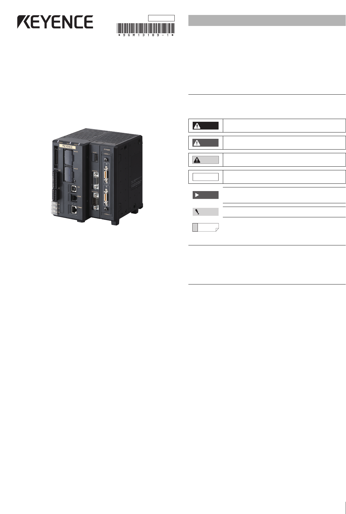
3햲 Parallel I/O connectorUse to connect the parallel input/output signals.햳 SD2 slot (upper), SD1 slot (lower)Insert an SD card.The lower slot (SD1) h
4Installing the Expansion UnitInstalling the Camera Expansion Unit (CV-X250/X270 only)Use a camera expansion unit CA-E800 (sold separately) to which
52 Connect the ground wire to the ground port.Connector SpecificationsThe specifications of the parallel I/O connector for the controller are as follo
6OUTPUT connector• Socket block:MC1.5/9-ST-3.5BK (Phoenix Contact)• Suitable wiringAWG 16 - 28 • Terminal block screw torque0.25 Nm or less INPUT conn
7*1 The letter at the end of the model number means the difference of the installed software function. For details, see the "CV-X Series User&apo
8Copyright (c) 2014 KEYENCE CORPORATION. All rights reserved.13189E 1104-1 96M13189 Printed in JapanController Unit CV-X200/X250/X270Unit: mmWith
Related products and manuals for Lighting Keyence CV-X200 Series
 (8 pages)
(1 pages)
(178 pages)
(2 pages)
(2 pages)
(1 pages)
(2 pages)
(2 pages)
(1 pages)
(1 pages)
(1 pages)
(4 pages)
(8 pages)
(1 pages)
(178 pages)
(2 pages)
(2 pages)
(1 pages)
(2 pages)
(2 pages)
(1 pages)
(1 pages)
(1 pages)
(4 pages)
© 2020, manymanuals.com. All rights reserved. | 0.116 s |
 Manymanuals.com
 Manymanuals.de
 Manymanuals.fr
 Manymanuals.it
 Manymanuals.pl
 Manymanuals.cz
 Manymanuals.es
 Manymanuals-pt.com
Comments to this Manuals