5
2 Connect the ground wire to the ground port.
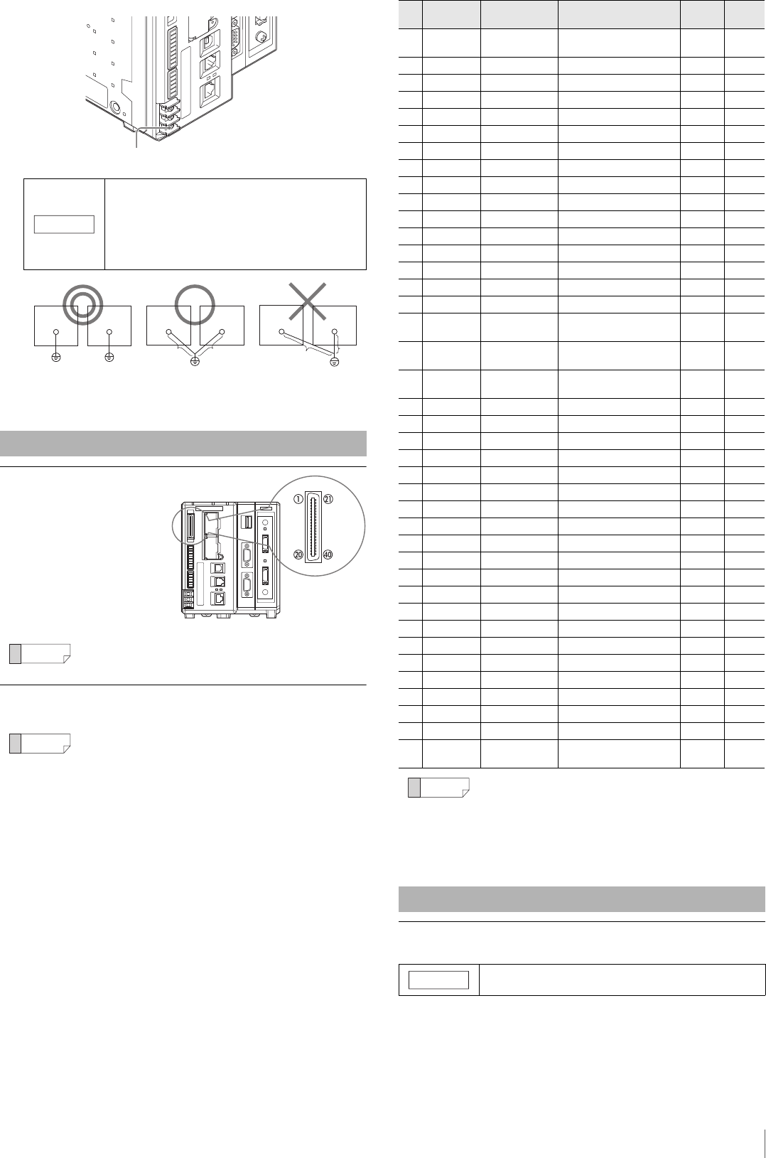
Connector Specifications
The specifications of the parallel
I/O connector for the controller
are as follows.
Connector
FX2B-40SA-1.27R
(Hirose Electric)
Color flat cable
UL20028-FRX-CF-40 (Fujikura,
equivalent wire gauge AWG28)
Pin layout: The cable color when the OP-51657
(option) is used.
Standard Specifications
Terminal block specifications for the controller are as follows.
• Ground each device separately.
• Use a D type ground.
• Keep ground resistance to 100 . or less.
• Keep the ground wire as short as possible.
• If it is not possible to ground each device separately,
ground them together. However, make sure that the
electrical cables are the same as shown below.
Parallel I/O Interface
In normal situations, use the specialized parallel connection cable
(3 m) OP-51657 (option).
*1 It is the default assigned value on the terminal where the
signal assignment can be changed. These assignments
may vary if the Global settings have been changed.
*2 For more details about the signal description, see the "CV-X
Series User's Manual
".
NOTICE
D-type ground (third ground)
(ground resistance 100 Ω)
A = B
D-type ground (third ground)
(ground resistance 100 Ω)
A > B
A < B
Device
Peripheral
Device
Peripheral
A
B
Device
Peripheral
A
B
No. Te r min al
name
Signal Signal Description
*2
Circuit
diagram
Cable
color
1 COMIN2 – Connector input common
terminal
–Brown
2 IN0 CMD_PARAM0 Command parameter bit 0 B Red
3 IN1 CMD_PARAM1 Command parameter bit 1 B Orange
4 IN2 CMD_PARAM2 Command parameter bit 2 B Yellow
5 IN3 CMD_PARAM3 Command parameter bit 3 B Green
6 IN4 CMD_PARAM4 Command parameter bit 4 B Blue
7 IN5 CMD_PARAM5 Command parameter bit 5 B Purple
8 IN6 CMD_PARAM6
*1
Command parameter bit 6
*1
BGray
9 IN7 CMD_PARAM7
*1
Command parameter bit 7
*1
BWhite
10 IN8 CMD_CODE0 Command input bit 0 B Black
11 IN9 CMD_CODE1 Command input bit 1 B Brown
12 IN10 CMD_CODE2 Command input bit 2 B Red
13 IN11 CMD_CODE3 Command input bit 3 B Orange
14 IN12 CST Command execution input B Yellow
15 IN13 RESET Reset B Green
16 IN14 PST
*1
Output data cycle input
*1
BBlue
17 COMOUT2 – Connector output common
terminal
– Purple
18 OUT0 ACK
*1
Verification of successfully
executed command input
*1
DGray
19 OUT1 NACK
*1
Verification of unsuccessfully
executed command input
*1
DWhite
20 OUT2 BUSY
*1
Busy signal
*1
DBlack
21 OUT3 CMD_READY Command input permission D Brown
22 OUT4 READY1 Trigger 1 input permission D Red
23 OUT5 READY2 Trigger 2 input permission D Orange
24 OUT6 OUT_DATA0
*1
Data output bit 0
*1
DYellow
25 OUT7 OUT_DATA1
*1
Data output bit 1
*1
DGreen
26 OUT8 OUT_DATA2 Data output bit 2 D Blue
27 OUT9 OUT_DATA3 Data output bit 3 D Purple
28 OUT10 OUT_DATA4 Data output bit 4 D Gray
29 OUT11 OUT_DATA5 Data output bit 5 D White
30 OUT12 OUT_DATA6 Data output bit 6 D Black
31 OUT13 OUT_DATA7 Data output bit 7 D Brown
32 OUT14 OUT_DATA8 Data output bit 8 DRed
33 OUT15 OUT_DATA9 Data output bit 9 D Orange
34 OUT16 OUT_DATA10 Data output bit 10 D Yellow
35 OUT17 OUT_DATA11 Data output bit 11 D Green
36 OUT18 OUT_DATA12
*1
Data output bit 12
*1
DBlue
37 OUT19 OUT_DATA13
*1
Data output bit 13
*1
D Purple
38 OUT20 OUT_DATA14
*1
Data output bit 14
*1
DGray
39 OUT21 OUT_DATA15
*1
Data output bit 15
*1
DWhite
40 COMOUT2 – Connector output common
terminal
–Black
• COMOUT2 for Pin 17 and Pin 40 are common.
• COMIN2 is a common terminal for input for the parallel I/O
connector.
• COMOUT2 is a common terminal for output for the parallel I/O
connector.
• Power source 0 V and COMIN1, COMIN2, COMOUT1,
COMOUT2, COMOUT_F+, and COMOUT_F- are all isolated.
Terminal Block Interface
Tightening with a force above the standard torque may cause
damage to the terminal block.
NOTICE
 (8 pages)
 Manymanuals.com
 Manymanuals.de
 Manymanuals.fr
 Manymanuals.it
 Manymanuals.pl
 Manymanuals.cz
 Manymanuals.es
 Manymanuals-pt.com
Comments to this Manuals